Machine Marking & Warning Symbols
Symbols and markings for the UK and EU markets
Marking of machines for the UK and EU can be confusing if the machine is manufactured in the USA. Requirements are different in the two markets.
Warning Symbols
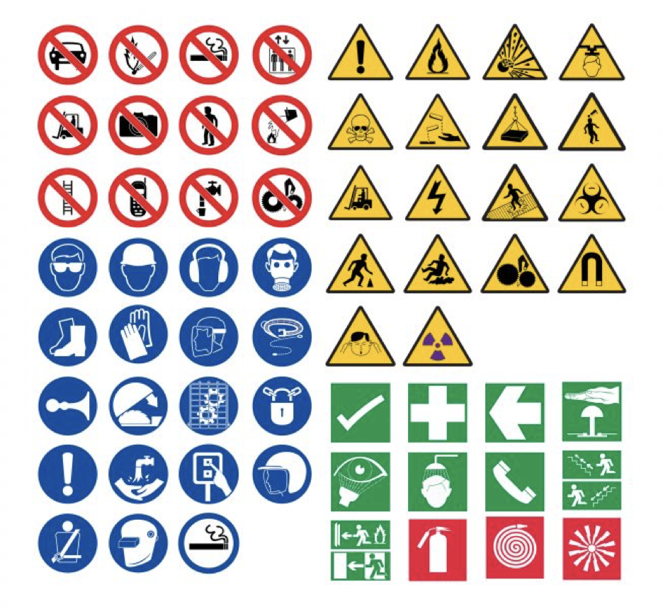
The UK and EU use ISO symbols only, because of the mandatory language requirements (must provide all text in local language).
New ANSI labels will be acceptable in the UK, since they are a combination ISO label and English text.
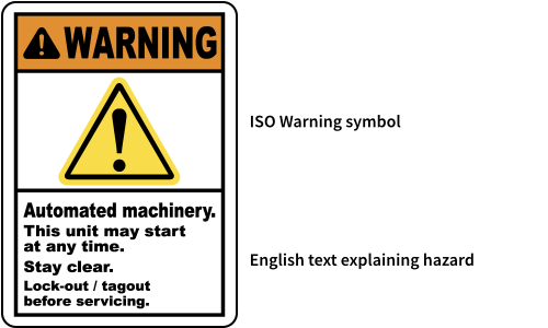
One of the first pages in the machine user manual should be the meaning of the warning symbols used on the machine. Their meaning and location of the hazard. Blue circles indicate a Mandatory Action. Yellow triangles indicate a warning, Red circles indicate a prohibition label.
Therefore a must for all machines is;

READ THE MACHINE INSTRUCTION MANUAL BEFORE USE
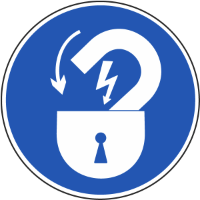
Mandatory Lock Out labels indicating the correct location of the Lock Out points.
 |
 |
 |
| Electrical Lock Out Point | Pneumatic Lock Out point | Crane Lifting Point |
 |
 |
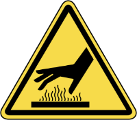 |
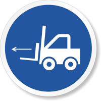
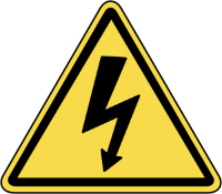
| Fork truck Lifting Point | Electrical Shock / Electrocution | Hot Surface Hazard |
 |
||
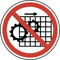
| Prohibition Labels - Do Not Operate Without Guards |
This is not an inclusive or exclusive list of the required symbols. In the EU, ISO labels are understood by all and do not need an explanation.
Machine Marking
Four mandatory requirements for the machine exist.
One. from the requirements outlined in the machinery directive;
All machinery must be marked visibly, legibly and indelibly with the following
minimum particulars:
- the business name and full address of the manufacturer and, where applicable, his authorised representative,
- designation of the machinery,
- the CE Marking (see Annex III),
- designation of series or type,
- serial number, if any,
- the year of construction, that is the year in which the manufacturing process is completed.
It is prohibited to pre-date or post-date the machinery when affixing the CE marking.
Two. from the Electrical requirements, outlined in EN 60204-1, section 16.4;The following information shall be legibly and durably marked in a way that is plainly visible after the equipment is installed on enclosures that receive incoming power supplies:
- name or trade mark of supplier;
- certification mark or other marking that can be required by local or regional legislation, when required;
- type designation or model, where applicable;
- serial number where applicable;
- main document number (see IEC 62023) where applicable;
- rated voltage, number of phases and frequency (if AC), and full-load current for each incoming supply.
It is recommended that this information is provided adjacent to the main incoming supply(ies). It is suggested these two requirements are combined into a single label and placed adjacent to the main incoming supply.
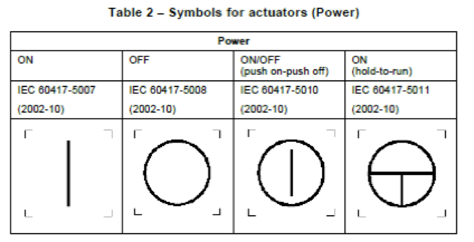
Three. From the Electrical requirements, outlined in EN 60204-1, section 10.2.2
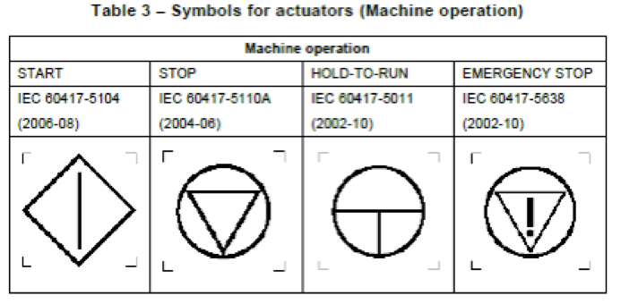
10.2.2 MarkingsIn addition to the functional identification as described in 16.3, recommended symbols to be placed near to or preferably directly on certain actuators are given in Table 2 or 3.
Four. From the Electrical requirements, outlined in EN 60204-1, section 16.5
16.5 Reference designationsAll enclosures, assemblies, control devices, and components shall be plainly identified with the same reference designation as shown in the technical documentation.
All components must be clearly identified in line with the electrical schematic. Components mounted in the electrical enclosure should be labelled on the backpanel. All cables must be labelled with a wire tag.